Placement of ice display areas in restaurants: How space is allocated for viewing, replenishment, and organization
Mark the locations for ice replenishment, container access, and table organization on the same diagram. The visual sense of abundance needs to be combined with convenience in removal and organization; If a large amount of decoration needs to be removed daily to manage the countertop, the layout must be re-evaluated.
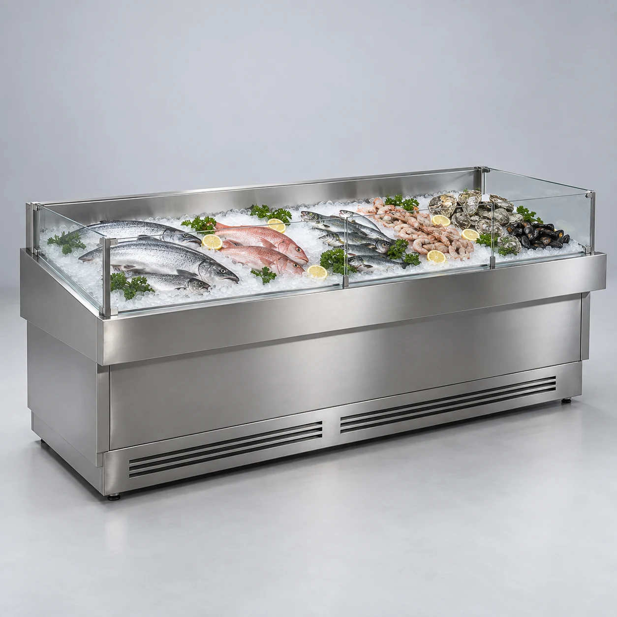
Start drawing by depicting the movement of people and items
Café restaurants want to optimize the display area centered around the ice table. The position of the ice table affects viewing, operation, and turnover simultaneously. When discussing the layout, if only a rectangle is placed on the floor plan, it’s easy to miss the movement ranges of doors, personnel, and containers. Mark the locations for ice replenishment, container access, and table organization on the same diagram. The ground conditions and related supporting facilities were confirmed by on-site personnel, and it is not possible to completely seal off the areas that need inspection using decorative barriers. The issue is not just ensuring the equipment fits properly, but ensuring it works well with surrounding processes during actual operation.
When drawing the first draft sketch, you can use lines to represent the movement of customers, staff, and items separately. Here, display containers, ice materials, zone labels, and food items that require independent management have different entry and exit methods and resting positions. Separate the regular paths from occasional paths, with special attention to actions that occur simultaneously during peak times; Positions that seem non-conflicting in normal use may need rearrangement when used by two people.
Distinguish between the equipment boundary and the operable boundary
The equipment diagram indicates a fixed footprint, but the actual layout must also accommodate handling, opening, organizing, and necessary service areas. First, confirm the display items and actual operation methods, then let equipment staff verify the ice table structure and supporting requirements. The depth of the countertop, the edge design, and container stability should be discussed in conjunction with daily organization practices. After including these compatibility conditions in the drawings, it is necessary to indicate which dimensions come from the equipment documentation, which are measured on-site, and which still need confirmation. Using different colors to distinguish sources can reduce discrepancies between the design drawings and on-site understanding.
The fixed positions on the layout diagram must be tested when items change. Take the ice platform as an example. Suppose the ice platform uses display containers of different depths, and the visual height after laying is similar, but the actual picking and placing stability is inconsistent. The contact methods between the container and the countertop, the organizing actions, and the edge relationships should be recorded separately, and then confirmed with the equipment personnel regarding the compatibility conditions. When transforming this scenario into observable steps, first establish the identities of items and personnel, then outline the points of interaction. After testing the arrangements, record where pauses are necessary, where accessibility must be maintained, and whether adjustments affect the next task. Confirm the device’s appearance, store decoration, and operating space on the same drawing, so on-site personnel can execute tasks consistently.
Make a justified choice between display and operation.
The visual sense of abundance needs to be combined with convenience in removal and organization; If a large amount of decoration needs to be removed daily to manage the countertop, the layout must be re-evaluated. Prepare two distinct placement schemes: one prioritizing the main viewing area, and another prioritizing minimizing repeated handling. Have users walk through each step individually, then record whether pauses, turns, or detours are required at each step. Comparisons should focus on actions, not just voting for the most attractive image.
When simulating peak usage, include adjacent processes together in the image. Take a freezer as an example: decorative barriers may enhance its appearance but hide areas requiring daily inspection. During design confirmation, both the appearance diagram and reachable location instructions should be provided, enabling an executable coordination between the interior design and maintenance efforts. When transforming this scenario into observable steps, first establish the identities of items and personnel, then outline the points of interaction. After testing the arrangements, record where pauses are necessary, where accessibility must be maintained, and whether adjustments affect the next task. Confirm the device’s appearance, store decoration, and operating space on the same drawing, so on-site personnel can execute tasks consistently.
Inspect the drawings during the business operation process, rather than only focusing on the opening status
Record the times of ice replenishment and table organization, while also observing whether containers tilt frequently, labels shift, or the surrounding area becomes damp. After identifying the phenomenon, first determine the location and operational context, then communicate and develop a solution. These records can help verify the layout in reverse: which areas often need to be temporarily cleared, which items have no fixed place, and which routes are occupied by restocking activities. For recurring issues, investigate whether it's due to poor positioning, insufficient labeling, or unclear responsibilities, and avoid attributing all problems to the equipment size.
Whether a layout can be used long-term also depends on how subsequent changes are managed. Taking the ice platform as an example, assume that labels on the ice platform are frequently adjusted during a business period. The reason may be that the actions of replenishment and organization do not follow a fixed order. You can first record the container corresponding to the label and its movement process, and then determine how to keep the organized positions consistent. When transforming this scenario into observable steps, first establish the identities of items and personnel, then outline the points of interaction. After testing the arrangements, record where pauses are necessary, where accessibility must be maintained, and whether adjustments affect the next task. Confirm the device’s appearance, store decoration, and operating space on the same drawing, so on-site personnel can execute tasks consistently.
Turn the arrangements tested in practice into a consensus on site
Verify the supply boundaries for the table surface, base, containers, and supporting components. The ice spreading effect in the sample diagram is different from the real business process. It should be confirmed through on-site demonstrations to see how employees carry out replenishment and organization. After the layout is finalized, assign numbers to the equipment and adjacent workstations, note the confirmation date, and ensure all relevant personnel use the same version of the drawings. When dimensions or configurations change, make corresponding modifications. Old diagrams should be clearly marked to prevent ongoing construction or receiving at expired positions on site.
BAONIER recommends providing floor plans, on-site photos, and representative container sizes together during product communication. For the ice shelf, a practical layout description should address where the item originates, who uses it, where it goes after use, and which areas must remain accessible. By translating these questions into specific actions, the equipment becomes a stable working position within the business process, rather than a source of constant detours and temporary adjustments.